Under Maintenance


SHAD ESPERON
MechanicalSystem Analyst
All Done With

SHAD ESPERON
MechanicalSystem Analyst
STEPPER MOTORS
TORQUE CALCULATION

In the spreadsheet below the motor torque required to accelerate a robot from rest its investigated together with the power required for the selection of the power source. Also, other parameters of importance are calculated as e.g. the time delay required for the "moveforward()" function to move the motor at the desired constant speed and also the speed in full step per seconds to be able to program it with a different approach.
The kinetics and kinematics employed takes into consideration a constant acceleration and a 0 degree inclined plane i.e. a flat surface for the sum of forces. The weight distribution was assumed as the total load divided by the total number of wheels but 10% more weight to the driver wheels to compensate for non uniform weight distribution in the system and therefore set a factor of safety for the torque required to move. Later, it can be adjusted experimentally (numerically) or with the aid of a computer software for accuracy.


PRODUCTION COST ANALYSIS
The spreed sheet below correspond to the production cost analysis for a motorcycle peg to be produced by volume. The main goal of the analysts its to identify the optimum production volume per day, i.e. how many pegs can be produced per day to reach the maximum efficiency in terms of cost without sacrificing the quality of the product and its performance.
To know the before mentioned data its necessary to know the production function of the company, which can be experimentally measured. In this case (do to the application) a production function its assumed and later compared with different production function to test a variety of manufacturing process and facilities or manufacturers. With the acquired data it was possible to identify the optimum pegs to be produced per day for a minimum cost per peg for a particular production function or manufacturer as show in the graph below (i.e. the intersection between peg unit cost vs production and marginal cost vs production).


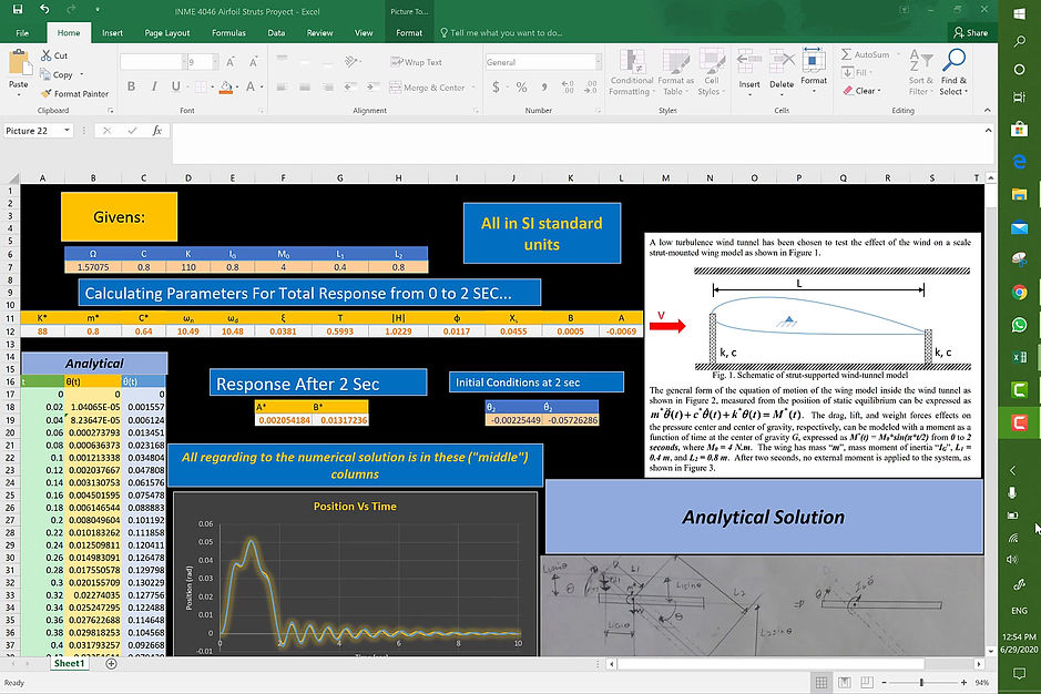
AIRFOIL HARMONIC EXCITATION
When analyzing mechanical system dynamics or any other system (pneumatic, electrical, magnetic etc.) from a finite element analysis perspective with the use of a software, it’s important to understand how the numerical solution method of the system works. In the spread sheet below you'll find the validation of a numerical method to calculate the response from 0 to 10 seconds of an aircraft airfoil due to a harmonic excitation that last 2 seconds. The airfoil its being test in a wind tunnel which provide the harmonic excitation, and the strut assembly consisting of a spring and a damper represent the elastic properties of the airfoil material.
To validate the numerical method, the analytical method was conducted first. The analytically derived equation of motion for the system led to a non-homogeneous, nonlinear, second order differential equation. To be able to solve the problem with the used numerical method, the equation was linearized assuming small angle rotations for the wing. (i.e. sin(θ)≈θ & cos(θ)≈1). Then the solution of the differential equation or the total response of the system its known, analytically. Then to calculate the numerical solution the Newmark method was used.